DATALINK EDIT GLOBAL PARAMETERS
In this panel you’ll be able to set the parameters to improve your farms performance and your virtual service custom features. The Edit Farm Action properties depend on the profile type that we’ve selected while the farm is created.
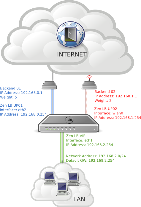
The DATALINK farm profile allows to create a routes based farm where the backends are uplink routers or gateways. This kind of farm profile is ready to share several uplink WAN router accesses using the load balancer as an uplink channel multiplexer (1 input and several router line outputs). Therefore, the DATALINK farms could be used as high available communication links and additionally could be used as bandwidth increase joining the amount of bandwidth between the routers backends links.
The specific options to be able to configure a DATALINK farm profile is detailed in the current section. In general, the farm will be restarted automatically with every change in a specific option in this farm profile.
The DATALINK farm profile provides a distribution panel with the following parameters:
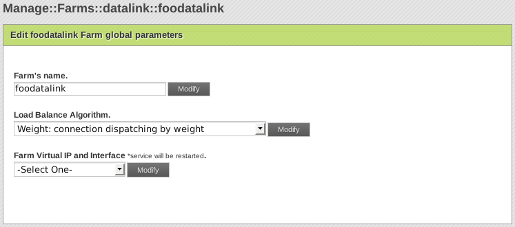
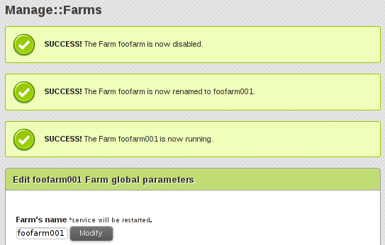
Farm’s name. It’s the identification field and a description for the virtual service. In order to change this item you’ve to modify the name field and press the Modify button. The load balancing service will be restarted automatically after applying this operation. Ensure that the new farm name is available, in another case an error message will appear.
Farm Virtual IP and Interface. These are the virtual IP address and network interface associated in which the virtual service for the farm will be bound and listening in the load balancer system. To make changes in these fields, ensure that the new virtual IP and network interface are not in use, as it will be exclusivity for this task. In order to apply the changes the farm service will be restarted automatically.
Load Balance Algorithm. This field specifies the load balancing algorithm to be used in order to determine the backend router. By default, weight algorithm will be the default selected algorithm.

Weight: connection linear dispatching by weight. Balance connections depending on the weight value, you have to edit this value for each real server. The requests are delivered through an algorithm to calculate the load of every server using the actual connections to them, and then to apply a linear weight assignation.
Priority: connections always to the most prio available. Balance all connections to the same highest priority server. If the first server is down, the connections will switch to the next prioritiest server. With this algorithm you can build an active-pasive cluster service with the real servers.
In order to get more specific information regarding this kind of farms, please refer to the official ZenLB documentation named “Quick Start Guide for uplinks load balancing with Zen Load Balancer”.
DATALINK EDIT REAL SERVERS CONFIGURATIONS
Once a new farm is created, you’ve to include the servers with the real services in order to deliver the client connections.
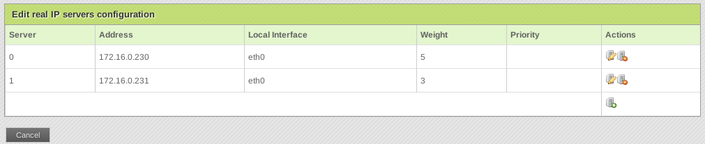
Under the Edit real IP servers table configuration you’ll be able to include the configuration backends for every backend and their specific parameters.
With a DATALINK farm profile you’ll be able to configure the following real servers properties:
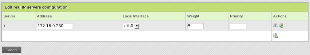
Server. It’s an automatic ID established to be an index for the real server. The system administrator can’t change this value.
Address. It’s the IP address of the real service. For datalink farms, the backends ip addresses will be the routers or gateways to be load balanced.
Local Interface. It’s the local network interface where the backend is connected to.
Weight. It’s the weight value for the current real server which is only useful if the Weight Algorithm is enabled. More weight value indicates more connections delivered to the current backend. By default a weight value of 1 will be set.
Priority. It’s the priority value for the current real server which is only useful if the Priority Algorithm is enabled. The priority value accepted is between 1 and 9, less value indicates more priority to the current real server. By default a priority value of 1 will be set.
With the  Save Real Server button you’ll apply the new configuration, or you’ll be able to
  cancel the process.

Once the real server configuration is entered, you’ll be able to edit the config throught the  Edit button or delete the configuration with the
  Delete Real Server button.
The server index is useful to identify the real server configuration for the current farm.
DATALINK VIEW STATUS
This action shows the actual state of backends, clients and connections that are being delivered from the virtual service to the real servers.
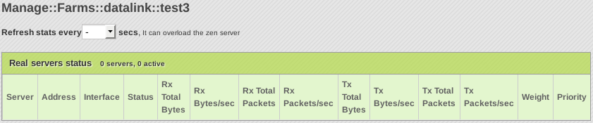
Refresh stats option will allow to refresh the status view every 10, 30, 60 or 120 seconds. It must be used with caution as this feature could overload the load balancer.
The Real Server Status table shows the state of every backend:
Server. It’s the backend identification number within the farm.
Address. It’s the real server IP address.
Interface. It’s the network interface where the backend is connected to.
Status. A red dot means that the current real server is down or blacklisted (it could be due to a connection error or due to farmguardian advanced checking), meanwhile a green dot means that the backend is online and delivering connections. A yellow dot means that the backend is in maintenance mode.
Rx Total Bytes. Total bytes received from a backend.
Rx Bytes/sec. Bytes per second received from a backend.
Rx Total Packets. Total packets received from a backend.
Rx Packets/sec. Packets per second received from a backend.
Tx Total Bytes. Total bytes transmitted from a backend.
Tx Bytes/sec. Bytes per second transmitted from a backend.
Tx Total Packets. Total packets transmitted from a backend.
Tx Packets/sec. Packets per second transmitted from a backend.
Weight. It’s the weight value established for every backend.
Priority. It’s the priority value established for every backend server.