These practical cases are a training guide to understand better how networking, security and high availability technologies work.
Firstly, try the following exercise:

Step 1. Install Zevenet CE from GIT, SF or Docker
            https://www.zevenet.com/community

Step 2. Create L4xNAT farm with 2 backends and NAT or DNAT mode
            https://www.zevenet.com/knowledge-base/

Step 3. Execute in a console of Zevenet CE and try to understand the result of:
            root# iptables -t mangle -n -L
            root# iptables -t nat -n -L
Doubts and comments in the official mailing list!
Answer
The load balancer is a network device in charge of ensure the traffic flow between the client and the backends or real servers, so 4 steps will be taken care in order to ensure the flows, packet per packet of the connection at layer 4:
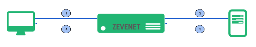
1. The packet from the client is sent from the client to the load balancer
2. The packet is sent from the load balancer to one selected real server or backend
3. The packet replies from the server to the load balancer
4. The packet is sent back to the client as a response
Zevenet layer 4 (LSLB – L4xNAT profiles) handle all these packets using netfilter subsystem through iptables and the network routing system.
For this reason, when configuring a DNAT mode farm and execute the iptables commands we can find rules generated in the tables mangle and nat of netfilter. Further information about Netfilter tables here .
In the PREROUTING chain of the mangle table it’s shown the rules that matches:
– All incoming packets from all sources or clients which destination is the virtual address and port of the service (in the example will be 192.168.101.250:443)
– Then mark the packets according to a certain algorithm, in this case is a weight based on a probability method.
root@zevenet:~# iptables -L -t mangle -n
Chain PREROUTING (policy ACCEPT)
target     prot opt source               destination
CONNMARK   all  --  0.0.0.0/0            0.0.0.0/0            CONNMARK restore
MARK       tcp  --  0.0.0.0/0            192.168.101.250      statistic mode random probability 1.00000000000 multiport dports 443 /*  FARM_app_1_  */ MARK set 0x20d
MARK       tcp  --  0.0.0.0/0            192.168.101.250      statistic mode random probability 0.50000000000 multiport dports 443 /*  FARM_app_0_  */ MARK set 0x20c
CONNMARK   all  --  0.0.0.0/0            0.0.0.0/0            state NEW CONNMARK save

Chain INPUT (policy ACCEPT)
target     prot opt source               destination

Chain FORWARD (policy ACCEPT)
target     prot opt source               destination

Chain OUTPUT (policy ACCEPT)
target     prot opt source               destination

Chain POSTROUTING (policy ACCEPT)
target     prot opt source               destination
Now that the incoming packets are marked, in the PREROUTING chain of the nat table we use the packet mark in order to change the destination address of the packet to one backend or another. For this example, the IP addresses 192.168.1.10 and 192.168.1.11 are the real servers.
root@zevenet:~# iptables -L -t nat -n
Chain PREROUTING (policy ACCEPT)
target     prot opt source               destination
DNAT       tcp  --  0.0.0.0/0            0.0.0.0/0            mark match 0x20c /*  FARM_app_0_  */ to:192.168.1.10:443
DNAT       tcp  --  0.0.0.0/0            0.0.0.0/0            mark match 0x20d /*  FARM_app_1_  */ to:192.168.1.11:443

Chain INPUT (policy ACCEPT)
target     prot opt source               destination

Chain OUTPUT (policy ACCEPT)
target     prot opt source               destination

Chain POSTROUTING (policy ACCEPT)
target     prot opt source               destination
The conntrack table manages the destination address translation and in the DNAT mode, the return packet is managed by routes as the load balancer will be the default gateway of the backends.
In the case of NAT, or SNAT as it’s commonly known, the conntrack manages not only the destination address translation but also the source address translation. In this case, the only difference with DNAT is that the replied packet it’s not managed by the routing system but by the conntrack table. So we can find just 2 new rules in the POSTROUTING chain of the nat table in order to perform the MASQUERADING with the virtual IP address of the farm.
root@zevenet:~# iptables -L -t nat -n
Chain PREROUTING (policy ACCEPT)
target     prot opt source               destination
DNAT       tcp  --  0.0.0.0/0            0.0.0.0/0            mark match 0x20c /*  FARM_app_0_  */ to:192.168.1.10:443
DNAT       tcp  --  0.0.0.0/0            0.0.0.0/0            mark match 0x20d /*  FARM_app_1_  */ to:192.168.1.11:443

Chain INPUT (policy ACCEPT)
target     prot opt source               destination

Chain OUTPUT (policy ACCEPT)
target     prot opt source               destination

Chain POSTROUTING (policy ACCEPT)
target     prot opt source               destination
SNAT       tcp  --  0.0.0.0/0            0.0.0.0/0            mark match 0x20c /*  FARM_app_0_  */ to:192.168.101.250
SNAT       tcp  --  0.0.0.0/0            0.0.0.0/0            mark match 0x20d /*  FARM_app_1_  */ to:192.168.101.250
Further doubts? Ask to the mailing list!