Contents
Global Settings for L4xNAT Farm Profile
The L4xNAT farm profile allows to create an LSLB farm that works at layer 4 with very high performance and much more concurrent connections than load balancer cores in layer 7 like HTTP farm profile. That layer 4 performance improvement is obtained instead of the advanced content handling that the layer 7 farm profile could manage.
Additionally, L4xNAT farm profile supports multiports with ranges and lists of ports against layer 7 farm profiles that only support one single port.
The specific options to be able to configure an L4xNAT farm profile is detailed in this section. It is recommended to use Farmguardian with this profile to check the status of each backend configured on the farm as this profile doesn’t implement any native health check.

You can know the farm status, restart, start or stop the farm from this view. Notice the Right Upper Corner buttons added for that purpose:
![]()
![]()
The Status color meaning is as follows:
- Green: Means UP. The farm is running and all backends are UP or the redirect is configured.
- Red: Means DOWN. The farm is stoped.
- Black: Means CRITICAL. The farm is UP but there is no backend available or they are in maintenance mode.
- Blue: Means PROBLEM. The farm is running but at least one backend is down.
- Orange: Means MAINTENANCE. The arm is running but at least one backend is in maintenance mode.
Those color codes are the same all over the graphical user interface. You can see them better explained in the LSLB Farms Section
Basic configuration
The parameters for basic L4xNAT farms profile are the following:
Name. It’s the identification field and a description of the farm service. In order to change this value, you’ve to stop the farm in the first place. Ensure that the new farm name isn’t already in use or an error message will appear.
Virtual IP and Port. These are the virtual IP address and/or virtual PORT in which the farm will be bound and listening inside the load balancer system. To make changes in these fields, ensure that the new virtual IP and virtual Port are not in use. After applying the changes the farm service will be restarted automatically.
In order to be able to select a range of virtual ports or a specific virtual port in L4xNAT farm profile, it’s mandatory to select a protocol type. In the case that protocol is set to “all”, the farm will be listening on all ports from the virtual IP, the virtual port will be not editable and set with the character *.
Once TCP, UDP or any other protocol is selected, it will be available to specify a port, several ports between, ports range between: or all ports with *. A combination of any other than * are also valid as well.
Advanced configuration
Protocol Type. This field specifies the layer 4 protocol to be balanced. By default, the farm will be available for TCP protocol.
- ALL. The farm will be listening for incoming connections to the current virtual IP and port(s) over all protocols. If you selected this option, the virtual port will be changed to ‘*’ value by default, and it not is possible to edit it, so the farm will be listening for all ports.
- TCP. Enabling this option, the farm will be listening for incoming TCP connections to the current virtual IP and port(s).
- UDP. Enabling this option, the farm will be listening for incoming UDP connections to the current virtual IP and port(s).
- SCTP. Enabling this option, the farm will be listening for incoming SCTP connections to the current virtual IP.
- SIP. Enabling this option, the farm will be listening for incoming UDP packets to the current virtual IP and port 5060 by default, and then will parse SIP headers for each packet in order to be correctly distributed to the backends.
- FTP. Enabling this option, the farm will be listening for incoming TCP connections to the current virtual IP and port 21 by default, and then will parse FTP headers for each packet in order to be correctly distributed to the backends. Two modes supported: active and passive.
- TFTP. Enabling this option, the farm will be listening for incoming UDP packets to the current virtual IP and port 69 by default, and then will parse TFTP headers for each packet in order to be correctly distributed to the backends.
- AMANDA. Enabling this option, the farm will be listening for incoming UDP packets to the current virtual IP and then will parse AMANDA headers for each packet in order to be correctly distributed to the backends.
- H323. Enabling this option, the farm will be listening for incoming TCP and UDP packets to the current virtual IP and port.
- IRC. Enabling this option, the farm will be listening for incoming TCP connections to the current virtual IP and port and then will parse IRC headers for each packet in order to be correctly distributed to the backends.
- NETBIOS-NS. Enabling this option, the farm will be listening for incoming UDP packets to the current virtual IP and port and then will parse NETBIOS-NS headers for each packet in order to be correctly distributed to the backends.
- PPTP. Enabling this option, the farm will be listening for incoming TCP connections to the current virtual IP and port and then will parse the PPTP headers for each packet in order to be correctly distributed to the backends.
- SANE. Enabling this option, the farm will be listening for incoming TCP connections to the current virtual IP and port and then will parse the SANE headers for each packet in order to be correctly distributed to the backends.
- SNMP. Enabling this option, the farm will be listening for incoming UDP packets to the current virtual IP and port and then will parse the SNMP headers for each packet in order to be correctly distributed to the backends.
NAT Type. This field indicates the NAT type which means how the layer 4 topology is going to operate. In order to select the option that better fits with your service and infrastructure will depend on the network architecture defined. By default, the farm will operate in NAT mode.
- NAT. The NAT mode or commonly named SNAT (source NAT) uses the load balancer IP as the backend connection source IP address, therefore the backend doesn’t know the client IP address at TCP, UDP or any other layer 4 protocol. In this way, the backend responds to the load balancer in order to send the response to the request. This topology permits to deploy a one-armed load balancer (load balancing with just 1 network interface).

- DNAT. The DNAT (Destination NAT) mode uses the client IP address as the backend connection source IP address, therefore the backend will respond directly to the client IP. In this case, the load balancer IP needs to be configured as the backend default gateway and isolate the backends network from the client service network. This topology is used to perform transparency between clients and backends.

- DSR. In DSR (Direct Server Return) mode the client connects to the VIP, then the load balancer changes its destination MAC address for the backend MAC address (the server must be on the same link media as the load balancer) and forward it to the backend without changing its IP address. The backend answers to the petition directly without passing through the load balancer.
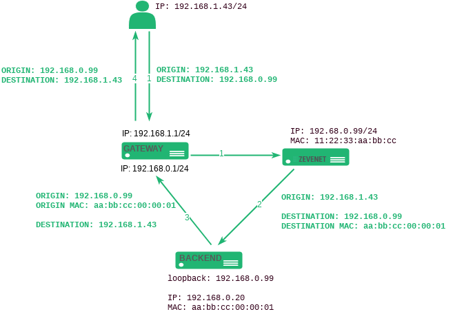
Requirements for DSR:
- VIP and backends need to be in the same network
- The Virtual Port and the Backend Port must be the same
- Backends need to configure a loopback interface with the same IP than the VIP configured in the load balancer and disable arp in this interface
# ifconfig lo:0 192.168.0.99 netmask 255.255.255.255 -arp up
- Needs to disable invalid ARP replies in the backend.
# echo 1 > /proc/sys/net/ipv4/conf/all/arp_ignore
# echo 2 > /proc/sys/net/ipv4/conf/all/arp_announce
- Stateless DNAT. In Stateless DNAT the load balancer switches destination address for the backend address and forward it to the backend as DNAT does, but it doesn’t manage any kind of connection information. DNAT configuration reduces the load on the system since it is performed in an early data path, being the most indicated NAT mode for layer 4 protocols with high load and not connection-oriented nor stream-oriented protocols as it is RTP or SYSLOG in UDP mode
Logs. To save the connections received on the farm enable the logging option. This is only recommended for debugging or monitoring purposes because it will slow down the amount of traffic that can be handled by the load balancer.
Services Settings
The service created in the L4 layer provides the following options to be configured in order to manage the data path and connections behaviour.
Load Balance Scheduler. This field specifies the load balancing algorithm to be used in order to determine the backend server. By default, the weight algorithm will be the default selected algorithm.

- Weight: connection linear dispatching by weight. Balance connections depending on the weight value that has been assigned to every backend. The requests are delivered using a probabilistic algorithm using the weight defined.
- Source Hash: Hash per Source IP and Source Port. Balance packets that match the same source IP and port to the same backend using a hash scheduler.
- Simple Source Hash: Hash per Source IP only. Balance packets that match the same source IP to the same backend using a hash scheduler.
- Symmetric Hash: Round trip hash per IP and Port. Balance packets that match the same source IP and port and destination IP and port, so it could hash a connection in both ways (during inbound and outbound).
- Round Robin: Sequential backend selection. It balances each incoming connection to a backend, switching between backends in a sequential manner.
- Least Connections: connection always to the least connection server. It selects the backend with the least number of active connections to ensure that the traffic load of the active requests is balanced to the most connections available real server.
Persistence
The Persistence options are the following.
Persistence Mode. This field determines if any persistence is used in the configured farm. By default, no persistence is used.
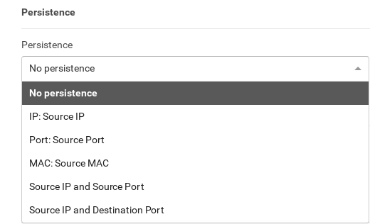
- No persistence. The farm will not use any kind of persistence between the client and the backend.
- IP: Source IP. With this option, the farm will assign the same backend for every incoming connection depending on the source IP address only.
- Port: Source Port. With this option, the farm will assign the same backend for every incoming connection depending on the source port only.
- MAC: Source MAC. With this option, the farm will assign the same backend for every incoming connection depending on link-layer MAC address of the packet.
- Source IP and Source Port. With this option, the farm will assign the same backend for every incoming connection depending on both, source IP and source port.
- Source IP and Destination Port. With this option, the farm will assign the same backend for every incoming connection depending on both, source IP and destination port.
Persistence session time to live. If any persistence is selected this field will be shown. This field value indicates the number of seconds that the persistence between the client source and the backend is going to be maintained.
Farmguardian
L4xNAT farms don’t provide a native health check for backends so the Farmguardian configuration is required in this kind of virtual services.
Some built-in or customized advanced health checks can be assigned to this service from any already created farmguardian checks.
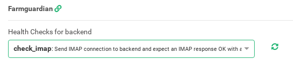
For further information about Farmguardian go to the Monitoring >> Farmguardian section.
Notice that after selecting the farmguardian, it will be automatically applied to the farm.
Backends
In this section, it can be seen all the configuration of already configured backends for the farm being modified and add new backends for the farm.
ADD BACKEND. This button will show the Add backend form to add a new backend to the farm configuration.
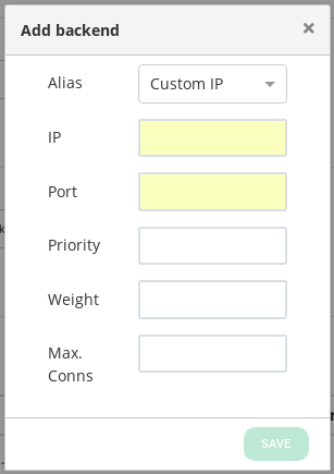
- Alias. This field shows the drop-down list with all the available backend aliases.
- IP. Network-Layer IP to be used when forwarding traffic to the backend.
- Port. Port to be used when forwarding traffic to the backend.
- Priority. It’s the priority value for the current real server, lower values are more priority. the initial value of priority is 1 and when a backend fails, +1 is added to this initial value, if the priority amount is minor or equal than the priority value for the backend then this backend will be used. When a backend is alive again -1 is reduced of the initial priority value.
- Weight. The backend weight for traffic balancing when the weight algorithm is set. It determines how preferable is the backend against other backends. This field allows integer values higher or equal than 1 (lowest value).
- Max. Conns. The number of connections that will be allowed to connect to the backend, if the limit is reached the new connections will be discarded.
Drop-down bulk actions list. If you click on the drop-down button on the right of ADD BACKEND, you will see the following actions which could be performed for one or more backend at the same time.
- Edit. Open the edit form, the same as the add form, to change any backend value.
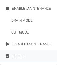
- Enable Maintenance. This action is available if the backend is up. It puts a real backend server in maintenance mode, so no new connections will be redirected to it. There are two different methods to enable the maintenance mode:
- Drain Mode. Keeps established connections and persistence if enabled, but will not admit new connections.
- Cut Mode. Directly drops all active connections against the backend, closing any connection between the backend and clients
- Disable Maintenance. This action is only available if the backend is maintenance mode. It will enable new connections to be forwarded to the backend server again.
- Delete. Delete the backend server of the virtual service. If the backend has an alias, the alias won’t be deleted.
Backends. This table shows all the backends already configured in the farm.
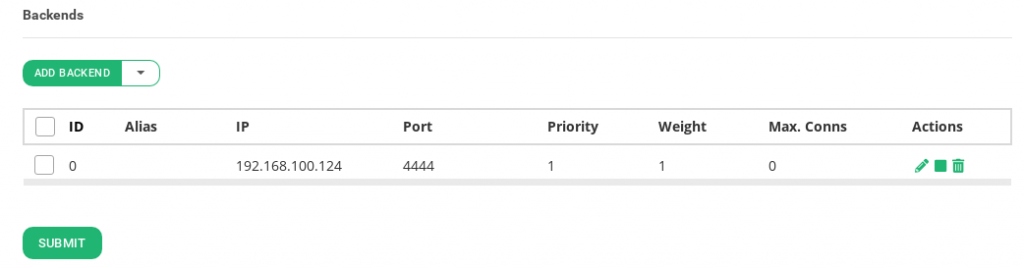
- ID. It’s the index that references the backend in the farm configuration.
- Alias. Backend alias if some alias has been previously defined for the backend.
- IP. The IP address of the backend, where the connection will be forwarded to.
- Port. It’s the port value where the connection will be redirected to at the backend. If blank value or ‘*’ value is set, connections will be redirected to the same port that was received.
- Priority. It’s the priority value for the backend server. The priority value accepted is an integer higher or equal than 1, less value indicates more priority to the current real server. By default, a priority value of 1 will be set.
- Weight. It’s the weight value for the current real server. More weight value indicates more connections delivered to the current backend. By default, a weight value of 1 will be set.
- Max. Conns. This value will be the maximum number of flows or established connections to a certain backend. If the limit of clients connected to a given backend has been reached then it’ll be refused and the client must reconnect to another suitable backend. The default value is 0, which means unlimited.
- Actions. The available actions per backend are:
- Edit. Open the edit form, the same as the add form, to change any backend value.
- Enable Maintenance. This action is available if the backend is up. It puts a real backend server in maintenance mode, so no new connections will be redirected to it. There is two different methods to enable the maintenance mode:
- Drain Mode. Keeps established connections and persistence if enabled, but will not admit new connections.
- Cut Mode. Directly drops all active connections against the backend, closing any connection between the backend and clients
- Disable Maintenance. This action is only available if the backend is maintenance mode. It will enable new connections to be forwarded to the backend server again.
- Delete. Delete the backend server of the virtual service. If the backend has an alias, the alias won’t be deleted.
IPDS Rules for L4xNAT farms
This section let you enable IPDS rules. The list shows different types of protection and a select box to enable them. For further information please go to the IPDS >> Blacklists rules, IPDS >> DoS rules or IPDS >> RBL rules specific documentation.
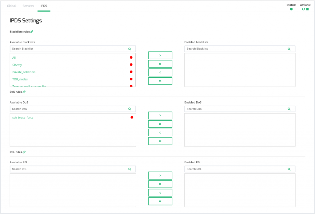
For each of the three types of IPDS rules, Blacklist, DoS and RBL, there are two tables, Available and enabled and a chain icon which redirects to its IPDS section. Under the Available table, it can be seen all the available rules of the same kind, that can be applied to the farm. Under the enabled table, it can be seen each rule of the same type applied to the farm, there is also a status ball for each rule which tells if the rule is stopped in red or running in green.
Each rule can be accessed clicking on its name which will allow you to change rules parameters or even start/stop the rule. It is not possible to create a new rule under this farm view, you should do it through the IPDS section.
You can add one rule, clicking on the desired rule and then on the right single arrow, or more than one, keeping shift key pressed and selecting the rules that you want to add, then you will need to click on the right single arrow. You can also add all available blacklists by clicking on the right double arrow.
To delete one or more rule, select them and click on the left arrow or click on the double arrow to remove all.